By Edoardo Genovese, Technical Development Manager RF – Europe, TTI
Today’s wireless technologies are at the heart of the smart revolution that’s changing the way we live and work. It’s common for connected “things” to support multiple wireless standards, such as cellular, Wi-Fi and Bluetooth, whilst also integrating GNSS for location and tracking. Here, we will consider the benefits of customising antennas versus ready-made wireless modules for such devices.
Multiple radios in tight spaces
Equipment designers are under enormous pressure to cram multiple radios within extremely tight spaces. Advancements in silicon and packaging technologies allow some parts of the radio circuit to occupy less space on the board. The antenna, however, is subject to laws of physics that allow only minimal flexibility. There are strict constraints on effective length to ensure resonance at the desired frequency, whilst multi-radio designs require adequate spatial separation between adjacent antennas to minimise unwanted coupling.
With these limitations in mind, recommended best practice is to prioritise the positioning of antennas that are the most susceptible to disruption by others. This suggests working initially on the cellular antenna, if fitted, followed by GNSS and, subsequently, Wi-Fi and Bluetooth antennas. Clearly, designers have more freedom to optimise the relative positions if antenna placement is considered early in product design and not tackled as an afterthought.
Antenna selection and placement
Choosing and placing an antenna on the circuit board demands a balance between achieving the smallest possible solution and ensuring adequate radiation efficiency in the appropriate frequency range. A planar inverted F antenna (PIFA) is a common choice for cellular radio. It is resonant at a quarter wavelength of the carrier signal, which allows for small size.
The PIFA should be placed at the corner of the board and the ground-plane length needs to be one-quarter the wavelength of the carrier signal. A PIFA for a low-band 5G frequency, say 617MHz, will need a ground-plane length of 120mm. It can be tempting to try reducing the length, to allow more space for placing other components on the board, but this will narrow the antenna bandwidth leading to sub-optimal performance.
Switched circuit antennas, such as those available from Kyocera AVX, offer an alternative that optimises the values of matching-circuit components to produce multiple narrowband responses; see Figure 1.
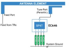
Figure 1: Different matching component values in switched-circuit antenna
The matching-circuit component values can be engineered to cover the entire desired frequency range; see Figure 2. This is a valuable technique to design a board-mounted antenna to cover a wide range of 3G, 4G and 5G frequencies for an IoT application.

Figure 2: Switched-circuit antenna covering a broad frequency range
More recently, loop antennas made from stamped metal and designed for surface-mount assembly also exist now. These have high radiation efficiency and maintain stable performance in the presence of nearby metal objects; for example, an RJ45 connector near the board.
With suitable matching components, these antennas can be designed to cover the full LTE band from 700MHz to 2.7GHz with high radiation efficiency. As a loop antenna, the ideal placement for these is the middle of the board edge, rather than a corner.
GNSS antennas
As far as GNSS antennas are concerned, ceramic patch and ceramic loop types are often used. Their circular polarised response ensures good sensitivity to the GNSS signal, which also has circular polarisation. This allows using small-size antennas, suitable for applications with size constraints. However, if the antenna is excessively small, polarisation can cease to be circular, impairing performance. Antennas as small as 9mm x 9mm are available, although 18mm x 18mm and 25mm x 25mm are more commonly used.
The directionality of the patch-type antenna makes this a good choice for fixed positions or where the antenna can be controlled to continuously face the sky, which is not always possible, especially in wearable devices or asset trackers. Here, ceramic loop antennas offer a better alternative, owing to their omnidirectional response. Also, these antennas can be smaller than ceramic patch types. As with any loop antenna, such an antenna should ideally be positioned in the middle of a board edge. For multi-constellation applications, multi-band ceramic-loop antennas are available off the shelf from various manufacturers.
An attractive new option in this category is the stamped metal PIFA. Abracon’s ProAnt brand antennas, for example, permit high sensitivity even if the orientation can’t be controlled to face the sky. Another great benefit is that the resonant frequency is relatively unaffected by nearby metallic components such as a chassis or enclosure. Hence, although larger than a ceramic alternative, the stamped metal PIFA can be positioned in a convenient location with no need for ground clearance. In addition, other components not related to the antenna circuit can be placed on the other side of the PCB. The antennas are surface mounted and are compatible with automated placement. As a PIFA, corner mounting is preferred, and the antenna can be placed on the far side of the board, away from the cellular antenna; see Figure 3.

Figure 3: Placement of cellular and GNSS PIF antennas
Wi-Fi/Bluetooth
After selecting cellular and GNSS antennas and ensuring their satisfactory positioning, consider the Wi-Fi and Bluetooth radios. Typically, a loop antenna is preferred for optimal performance, with greatest immunity to detuning by the presence of nearby antennas and components. They are well suited for wearable products, such as smart watches, and can be ceramic or stamped metal types. For operation in the 2.4GHz frequency range, the half-wavelength dimension is 62mm.
Best performance optimisation
When the antennas have been selected and their location nominally determined, further work is needed to finalise their position to ensure their optimal performance. Adequate isolation between antennas is critical, typically quantified by the S2,1 relationship between adjacent antennas; see Figure 4.

Figure 4: Using S2,1 parameters to assess antenna spatial separation
The typically tight space constraints in portable and mobile applications mean some level of interaction is unavoidable. However, coupling between any two antennas causes a proportion of the antenna’s efficiency to be lost since a portion of power is coupled to the adjacent antennas instead of being radiated. In the worst case, excessively strong coupling can cause interference. A GNSS receiver can be particularly susceptible to the influence of an antenna close by. In this case, an S2,1 of at least -15dB or, better still, -20dB, is recommended.
It is also vital to investigate any detuning effects caused by objects in the near field of any of the antennas in the system. Specific antenna types, such as PCB-trace and wire antennas are more susceptible to detuning. Although loop-type antennas, in particular, are generally robust and can maintain performance under non-ideal conditions, the effects of objects such as the plastic enclosure can shift the antenna’s resonance point away from the desired frequency and, ultimately, reduce the signal strength at the receiver. Other hazards include the effects of cables and nearby metal objects or surfaces, which can couple with antennas and reduce their efficiency. The effect of the cover glass of a display can be particularly acute. However, the stamped metal antennas can be more resistant to these effects.
On the other hand, internal FPC or PCB cable antennas are not optimised to operate in free space. Instead, placement next to a PCB or housing is expected. Some types are available with an optional foam layer to provide extra decoupling between the antenna and an adjacent surface – particularly a plastic, glass or metal surface – to optimise the efficiency.
The benefits of using wireless modules
Instead of developing a custom design from scratch, there is a wide range of wireless modules available that are pre-certified for a given application. Most contain the antennas mentioned earlier, but there are others from Panasonic and Murata that offer more, such as ZigBee and Thread.
Providing added flexibility for connectivity in IoT battery-driven applications where low power consumption is crucial, combination wireless modules exist. They will enable simultaneous yet independent operation of, say, Wi-Fi for when high data rates are required and, when not needed, Bluetooth Low Energy.
Comprehensive evaluation kits support rapid prototyping with the wireless modules, streamlining the layout and optimisation processes and thus helping designers quickly achieve an implementation that will perform well. With minimal fine tuning, a solution capable of passing mandatory product tests can be achieved.
An additional benefit is that the module’s lifecycle can be longer than a custom antenna solution – consider the risk of one of the antennas becoming obsolescent – which could be useful for wearable home healthcare smart devices. Last but not least, wireless modules will reduce production time, procurement and inventory, resulting in further savings.
Due consideration to antenna design
Today’s personal electronics and IoT devices typically rely on multiple wireless standards for networking, data exchange and context sensing. With multiple radios coexisting in a confined space, antenna selection and layout is more complicated than in a simple single-radio system. There are options that will help designers achieve the best possible trade-off between PCB size, antenna radiation efficiency and receiver sensitivity (which influence application energy efficiency), cost and ease of manufacture.
As with any radio design, testing in a realistic environment – such as ensuring the board is correctly installed in the intended enclosure and in proximity to any objects that might affect antenna performance – is essential to verify system functionality and prevent failures later in the development process. Overall, giving due consideration to antenna design at an early stage of development can help avoid difficult repositioning challenges and costly delays later in the project.
On the other hand, multiple vendors offer wireless modules for the widely-adopted protocols, such as Wi-Fi or Bluetooth. These help free up valuable design resources and alleviate the headache of specialist RF engineers balancing overall performance and efficiency. They also come fully tested and pre-certified, enabling a faster route to market.
TTI Europe stocks a wide range of antennas and wireless modules from Kyocera AVX, Abracon, Molex, Panasonic, Pulse, TE and others. TTI Europe’s dedicated team of RF specialists can also help with technical advice and guidance, for custom RF design or one using ready-made wireless modules.